
Autonomous Aerial CPR Robot
Overview
Cardiac arrest is a critical medical emergency where every second counts. While Cardiopulmonary Resuscitation (CPR) is the standard first-aid treatment, manual CPR is physically exhausting, often inconsistent in quality, and difficult to sustain for the required 30+ minutes. Furthermore, traffic and terrain can delay the arrival of emergency medical services.
This project proposes a Flying Mechanical CPR Robot—an autonomous aerial vehicle capable of flying directly to a patient’s location and performing mechanical chest compressions. This system aims to solve the “last mile” problem in emergency response, ensuring consistent, high-quality CPR delivery before an ambulance arrives.
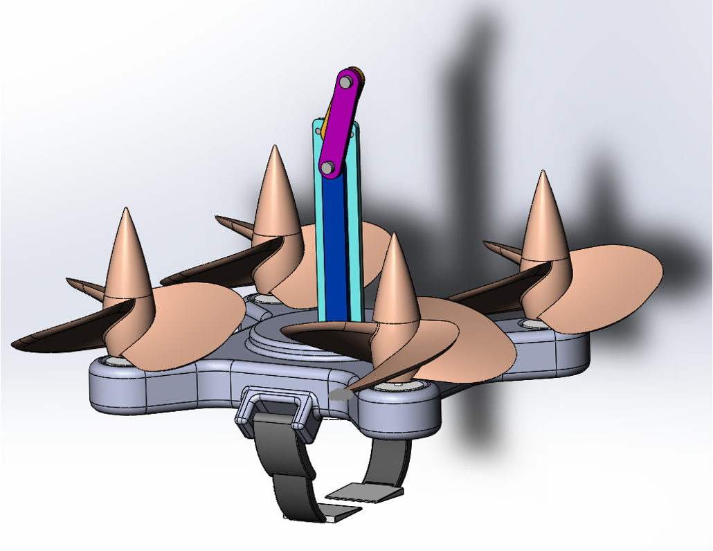
Fig 1: Concept of the aerial robot deploying to perform CPR on a patient.
Demonstration of the aerial CPR robot design.
System Workflow
The robot operates through a multi-stage autonomous workflow designed to minimize human intervention and maximize speed:
- Deployment: Upon receiving an emergency signal, the drone takes off and navigates to the GPS coordinates.
- Visual Targeting: Using onboard cameras and computer vision, the robot identifies the patient and determines the optimal landing position.
- Positioning: The drone lands on the patient’s chest area, utilizing its landing gear to stabilize against the body.
- Execution: The mechanical arm deploys to perform rhythmic chest compressions according to international CPR standards (depth and frequency).
In this project phase, we focus on the control algorithms and simulation of the compression and holding mechanism to ensure safe and effective operation.
Control & Simulation
To ensure patient safety and compression efficacy, we developed a robust control system validated through MATLAB/Simulink simulations.
Dynamics Modeling
We modeled the robot’s kinematics and dynamics to account for the reaction forces generated during chest compressions. The system utilizes:
- Inverse Kinematics Solver: To calculate the necessary joint angles for precise end-effector positioning.
- Inverse Dynamics Solver: To compute the required motor torques.
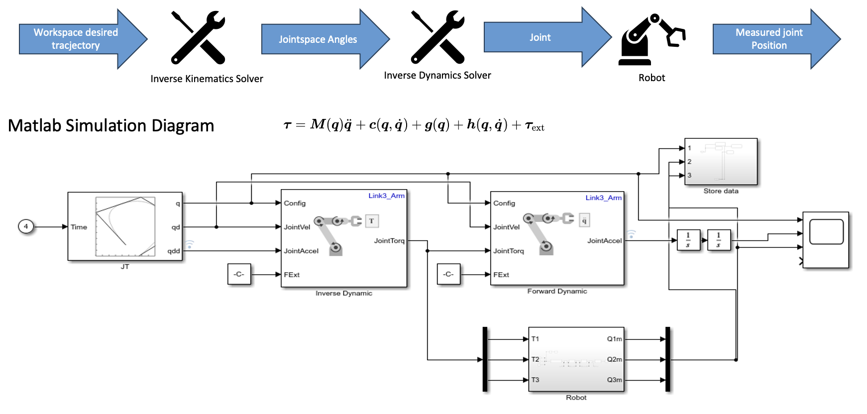
Fig 2: Dynamics simulation.
PID Control Strategy
A PID (Proportional-Integral-Derivative) controller was implemented to manage the position and force of the compression arm. This ensures:
- Disturbance Rejection: The system maintains stability even when subjected to external disturbances (e.g., wind or patient movement).
- Precision: The compression depth is tightly regulated to prevent injury while ensuring effective blood circulation.
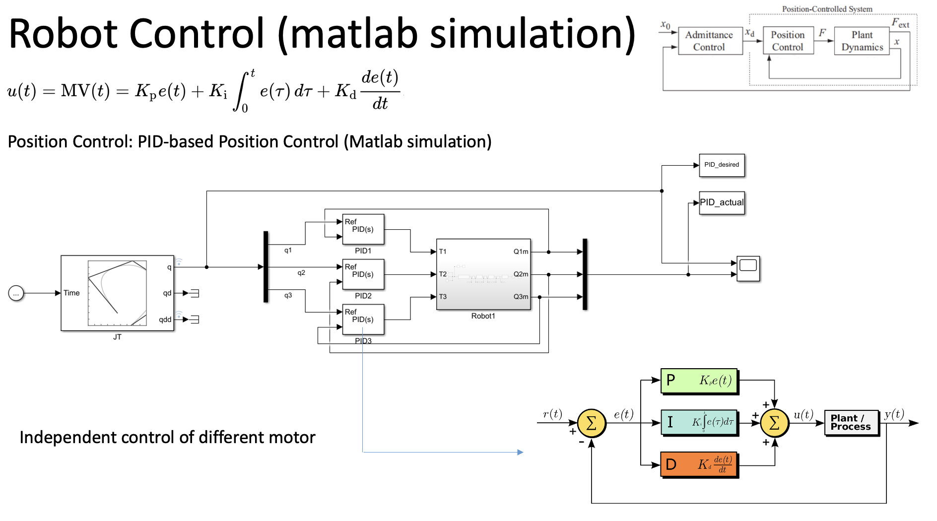
Fig 3: Control System Block Diagram
System response with PID control, showing stabilized trajectory tracking.
Results
Simulation results demonstrated that the PID-controlled system could effectively reject disturbances and track the desired compression trajectory. The system maintained stable operation, proving the feasibility of an aerial manipulator performing high-force tasks like CPR.
Future Work
- Computer Vision Integration: Implementing real-time patient detection and pose estimation.
- Prototype Fabrication: Building a physical scale model to validate the flight and compression mechanics.
- Safety Protocols: Developing emergency stop mechanisms and soft-landing protocols to protect the patient.